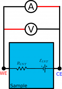
All electrochemistry practitioners should be familiar with open-circuit measurements. This is the case when electric current in the circuit vanishes. It is easily achieved by breaking the circuit as it is done with Open Circuit Potential (OCP) measurements, for example.
The opposite case is when one would like to have electric voltage to vanish between two distinct points of a circuit.
Then one would have a short-circuit between the points.
Two-electrode example
This idea is best shown on a two electrode example

Sample in the example has two contacts: on the left and on the right hand side.
Internally, it consists of some serial resistance $R_{INT}$ and an electromotive force $\mathcal{E}_{INT}$ .
The potentiostat connected to the sample is essentially represented by a voltmeter V and ammeter A, where red wires indicate positive terminals.
One may wonder what would be the electric current generated by the sample itself without any interference from external bias potentials. In such a case, the experiment should run with the bias potential $E_{SC}=0\; \mbox{V}$. It is, in the chrono-amperometry (CA) experiment the voltmeter should maintain 0 V.
Such a setup is important, for example, in IMPS measurements of DSSC samples where the diffusion model of majority carriers propagation is tested. Any non-zero bias potential would either affect the cell sensitivity to light or/and add unwanted drift component to the diffusion.
With the short-circuit arrangement one can write the value of the current
$$
I_{SC} = \frac{\mathcal{E}_{INT}}{R_{INT}}.
$$
The same current would flow if one just shortened the two sides of the sample with a copper wire.
Three-electrode picture
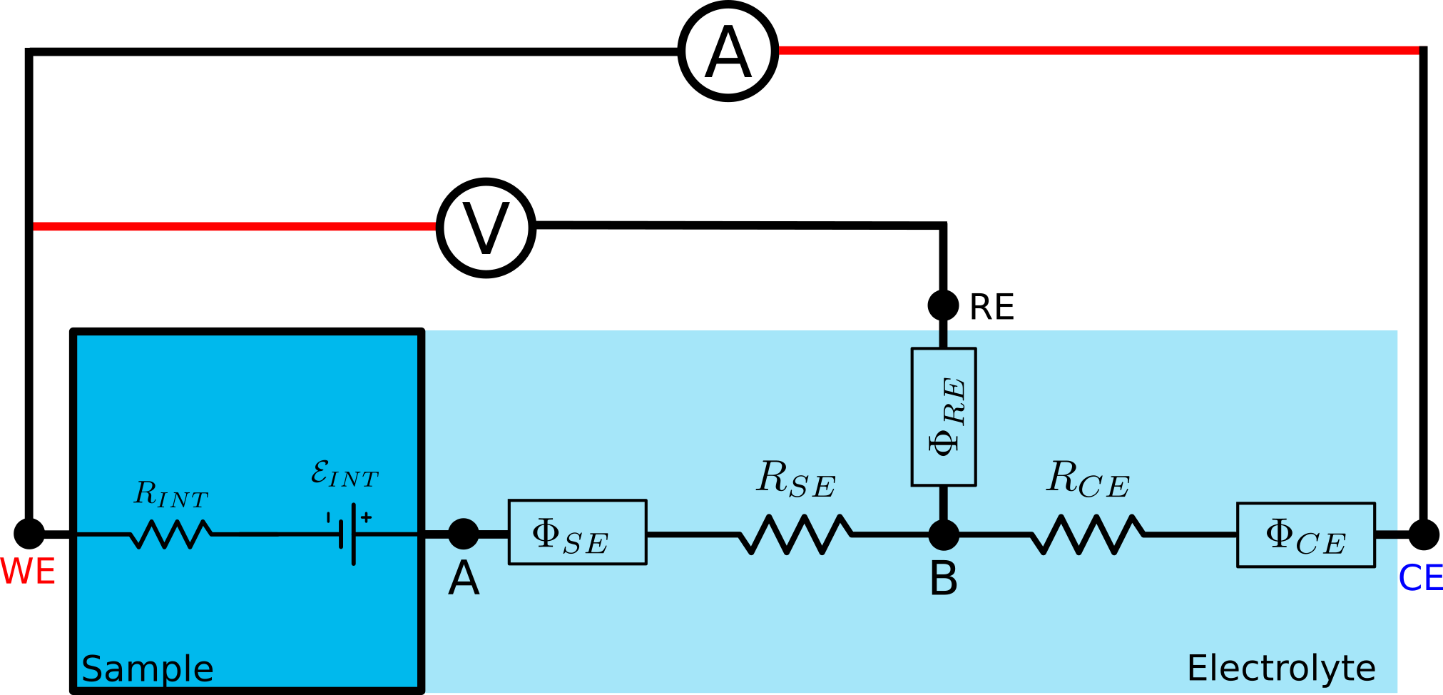
The same sample as above when introduced into three electrode setup will show somewhat more involved picture

The sample, as soon as it has contact with electrolyte, will start dissolving its ions in it or/and adsorbing ions of opposite charge on its wet surface. This will lead to the development of electrode potential $\Phi_{SE}$ and the resistance $R_{SE}$ at the sample-electrolyte interface.
Similar phenomena will lead to $\Phi_{CE}$ and $R_{CE}$ at the counter electrode (CE).
The third electrode, reference electrode (RE) is used to factor out counter electrode properties from the measurements of the sample. It comes with its own half-cell potential $\Phi_{RE}$.
Surprising inconvenience
Lets perform a measurement on the shorted sample. As in the two-electrode example we should have zero voltage between points WE and A. Then one should recover the short-circuit current
$$
I_{SC} = \frac{\mathcal{E}_{INT}}{R_{INT}}.
$$
So, what bias potential $E_{SC}$ should one select in the CA measurement to achieve that? Or, in other words, what voltage should be maintained on the voltmeter to have proper short-circuit conditions? Of course, neither $\mathcal{E}_{INT}$ nor $R_{INT}$ are known beforehand, so one doesn’t know what short-circuit current actually is.
Other measurements, like OCP, would give some constraints like
$$
V_{OCP} = -\mathcal{E}_{INT} + \Phi_{SE} - \Phi_{RE}
$$
or in CA with short-circuit current
$$
E_{SC} = V_{OCP} + I_{SC} (R_{INT}+R_{SE}),
$$
but one cannot separate the serial resistances $R_{INT}$ form $R_{SE}$ and potential steps $\mathcal{E}_{INT}$ and $\Phi_{SE}$. No matter how one will rearrange the setup, the two pairs are inseparable.
Thus, if the author is sane, there is no way of telling what the $E_{SC}$ is. So, no way to arrange for short circuit scenario in the three-electrode setup!
This is the inconvenient part. It gets worse …
The disaster
Oh, well! If one submerges the sample in electrolyte, the sample’s properties change. Instead of whining just live with it and incorporate sample-electrolyte interface characteristics into the sample. I.e., after the contact with electrolyte
$$
R_{INT} \to R_{INT} + R_{SE}
$$
and
$$
\mathcal{E}_{INT} \to \mathcal{E}_{INT} - \Phi_{SE}.
$$
Then instead of trying to shorten points WE and A one can shorten the points WE and B.
For the sample in electrolyte, the expected short circuit current becomes
\begin{equation}
I_{SC} = \frac{\mathcal{E}_{INT}-\Phi_{SE}}{R_{INT}+R_{SE}}.
\label{bull}
\end{equation}
This current is achieved for bias potential
\begin{equation}
E_{SC} = -\Phi_{RE}.
\label{shit}
\end{equation}
Such a simple result!
Even too simple, indeed. Any single electrode (half-cell) potential should be treated as not measurable. Only differences of electrode potentials make sense. In that case, one can pick out a standard electrode like S.H.E. (standard hydrogen electrode) and use it consistently to express all electrode potentials with respect of that standard electrode. The absolute potential (4.44 V$^*$ 🙂) of the standard electrode remains unknown although its standard potential is zero due to the convention only.
So, if an Ag/AgCl electrode has the standard potential 0.222 V it means that the absolute potentials of the electrode
is 0.222 V + absolute potential of S.H.E., which could be anything. So could the bias potential $E_{SC}$ given by Eq. $\ref{shit}$.
Thus the electrode potentials should always enter equations in pairs !
The equation Eq. $\ref{shit}$ for $E_{SC}$ above is meaningless. So is the Eq. $\ref{bull}$ and for the same reason.
It turns out, we cannot make short circuit between points WE and RE either.
$^*$ Absolute electrode potentials should not be of concern in regular day-to-day electrochemical measurements. That is what standard hydrogen electrode potential was introduced for.