The color determination of samples under illumination is a complex endeavor. There are several layers of computation
interlaced with necessary, and still not obvious, assumptions made to confine the problem into several numeric quantities.
White reference
Our Micro Fading Testers compute and record color changes of a sample due to light induced dye fading .
In order to provide a quantitative measure of the change, the instrument measures a spectrum of light reflected from a white reference $w(\lambda)$ and then spectra of light reflected from the sample $s(\lambda, t)$ at various times $t$, computes the reflectances
\begin{equation}
R(\lambda, t) = \frac{s(\lambda,t)}{w(\lambda)}
\label{refl}
\end{equation}
and converts them to, so called, CIELab color space.
CIELab color space
The coordinates in the CIELab color space are: $L^*$, $a^*$ and $b^*$. The asterisks are used with the coordinate’s symbols, so they are distinguished from another color space with the same symbols.
You can see the graphic representation of the CIELab color space in the MFT software’s “CIE Lab” tab.
Distances in the CIELab color space are color perceptions differences. In other words, if two points in the CIELab color space are close to each other, a human eye (and, hopefully, a brain behind it) would also perceive the corresponding colors as close.
The color perception part in the CIELab involves properties of a standardized human eye which are derived from yet another color space: CIEXYZ.
CIEXYZ color space
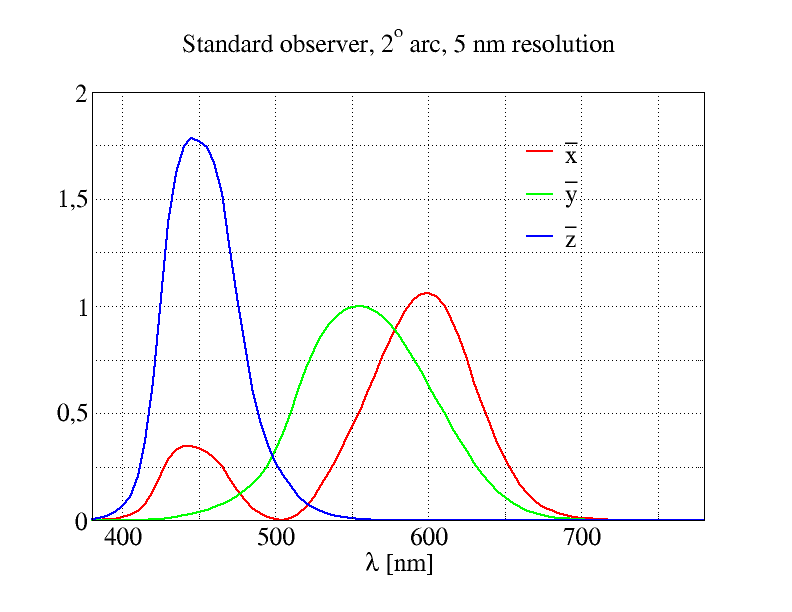
The CIEXYZ space relays on the three color matching functions: $\bar x(\lambda)$, $\bar y(\lambda)$ and $\bar z(\lambda)$ that capture human eye sensitivity to various spectral stimuli.
Self-luminous source
If one has a light source described by a spectral radiance $L(\lambda)$ then a human standardized eye or the standard observer would sense the three stimuli:
\begin{equation}
X = \int L(\lambda) \bar x(\lambda)\mbox{d}\lambda
\end{equation}
\begin{equation}
Y = \int L(\lambda) \bar y(\lambda)\mbox{d}\lambda
\end{equation}
\begin{equation}
Z = \int L(\lambda) \bar z(\lambda)\mbox{d}\lambda,
\end{equation}
where the integrals run in the full range of the color matching functions, i.e., from 380 nm to 780 nm.
Unfortunately, in the case of microfedometry this is not applicable since a sample is a reflective rather than emissive source of light.
Reflective source
In the case of an emissive source above, the light properties where given by a single function $L(\lambda)$. For the reflective source one has to consider:
- an illuminant function $I(\lambda)$ which characterizes the light source used to illuminate the sample and
- a reflectance $R(\lambda)$ which characterizes sample’s ability to reflect incident wavelengths of light.
The necessity for the distinction is easy to understand. If one has a white sample, $R$, and illuminates it with a green light, $I$, then it would appear green to an observer. Or, if one has a red sample, $R$, and illuminates it with a green light, $I$, then the observer will see it black because the sample reflects only red light.
The three human eye impressions would now be given by
\begin{equation}
X = \frac{100}{N}\int R(\lambda) I(\lambda) \bar x(\lambda)\mbox{d}\lambda
\label{ciex}
\end{equation}
\begin{equation}
Y = \frac{100}{N}\int R(\lambda)I(\lambda) \bar y(\lambda)\mbox{d}\lambda
\label{ciey}
\end{equation}
\begin{equation}
Z = \frac{100}{N}\int R(\lambda) I(\lambda) \bar z(\lambda)\mbox{d}\lambda,
\label{ciez}
\end{equation}
where the normalization factor is given by
$$
N = \int I(\lambda)\bar y(\lambda)\mbox{d}\lambda
$$
for $\lambda \in [380\; \mbox{nm}, 780\; \mbox{nm}]$. The factor 100 converts the reflectance defined in Eq. $\ref{refl}$ into per cents.
Standard illuminants
Since the CIEXYZ coordinates for reflective samples depend on both the sample and the illuminant properties, it is convenient do define some common illuminants, so that the samples could be compared between laboratories without need to remeasure them in a lab’s particular setup. That is why several series of standard illuminants have been defined.
D65 illuminant
This illuminant is very popular in the conservation science community as it is supposed to represent daylight at noon (in Europe).
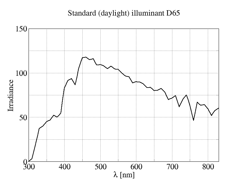
The spectral range is from 300 nm to 830 nm. It should be used if one wants to compute “real” colors of a sample, i.e.,
the colors of the sample in daylight.
LED-B1 illuminant
This illuminant corresponds to a standardized white LED light at 2733 K. We have chosen that illuminant as default for internal color computation in the MFT software (version 3.0 and higher) as it has the least pronounced blue peak in irradiance of all LED illuminants.
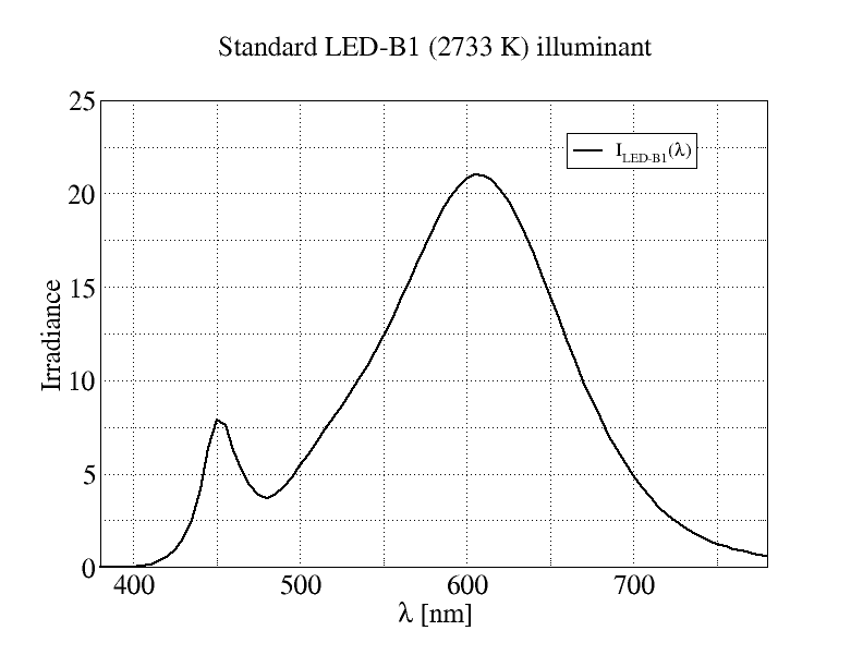
In Eq. $\ref{ciex}$, Eq. $\ref{ciey}$ and Eq. $\ref{ciez}$, the illuminant is given by the curve plotted above
$$
I(\lambda) = I_{\mbox{LED-B1}}(\lambda)
$$
This illuminant gives the colors that are yellowish as compared with daylight. In our regular single LED MFTs, the 2700 K or 3000 K LED is used for both aging and color readout. If someone would look at the very spot of the illuminated part of a sample, one would get impression of yellowish colors, due to the yellowish phosphor-converted blue illumination of a warm white LED.
More LED illuminants
In art galleries LED illumination of art pieces becomes commonplace. To get rid of yellowish appearance, the paintings are illuminated with higher color temperature LEDs.
Scientific grade MFTs and customized regular (single LED) MFTs also use white LEDs with higher color temperature.
That is why our software version 3.0 and newer also allows for a choice of standard LED illuminants from B1 to B5.
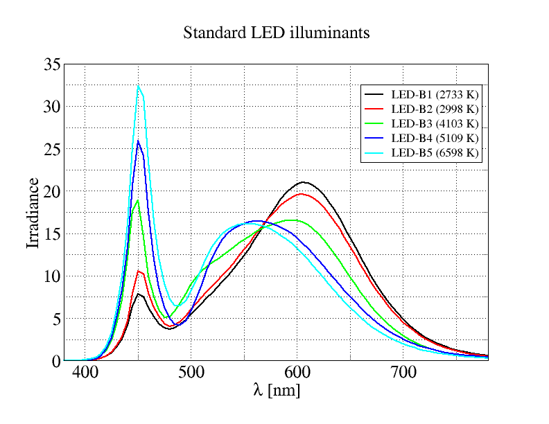
The LEDs standard illuminants have the advantage over the daylight (D65) illuminant, because they match the spectral characteristics of LEDs much better. In particular, they include the light intensity cut-off for wavelengths shorter than 420 nm. That makes aging curves less noisy because the noise in reflectance $R(\lambda)$ at the spectrum edges of the available light source is tempered by the illuminant.
Back to CIELab
The CIELab color space coordinates are build from CIEXYZ coordinates in the following way:
$$
\begin{equation}
L^{*} = 116f\left(\frac{Y}{Y_n}\right) - 16
\label{cieL}
\end{equation}
$$
$$
a^{*} = 500\left ( f\left(\frac{X}{X_n}\right ) - f\left (\frac{Y}{Y_n}\right ) \right )
$$
$$
b^{*} = 200\left ( f\left(\frac{Y}{Y_n}\right ) - f\left (\frac{Z}{Z_n}\right ) \right ),
$$
where
$$
f(t) =
\begin{cases}
\sqrt[3]{t} & t > \delta^3 \\
\frac{t}{3\delta^2} + \frac{4}{29} & t\le \delta^3,
\end{cases}
$$
with $\delta = \frac{6}{29}$.
The reason for making the CIEXYZ to CIELab transition is that the later is supposed to be uniform, i.e., a small change in the $L^{*}$, $a^{*}$, $b^{*}$ coordinates results in the same color perception change independent of the position in the CIELab color space.
White reference tristimuli $X_n, Y_n, Z_n$
While the $X,Y$ and $Z$ coordinates correspond to the measured sample, the $X_n, Y_n$ and $Z_n$ are the color coordinates of a white reference placed in the same spot as the sample and illuminated with the same illumination.
Following the Eq. $\ref{refl}$, the reflectance of the white reference is
$$
R(\lambda) = \frac{w(\lambda)}{w(\lambda)},
$$
which is unity in the entire range of wavelengths available for the illuminating LED.
From the Eq. $\ref{ciey}$
$$
Y_n = 100.
$$
This should be a maximum possible value for $Y$ because all samples will reflect at most the same amount of light of a given wavelength as the white reference.
In practice, white reference diffuses all incoming light into an entire available solid angle. Only a small fraction of that diffused light is captured by the detector in the MFT’s spectrometer.
It may happen that a rough sample surface would work as a mirror that reflects more light into the detector than the white reference . In that case, the value of $L^{*}$, Eq. $\ref{cieL}$, may exceed the maximum theoretical value of 100.
In such a case, it is enough to move the sample a bit with respect to the illumination spot to recover proper $L^{*}$ coordinate values.
Hybrid approach
This section of the post is relevant for early MFT software versions older than 3.0.
In the time when MFTs where developed, there was no standard LED illuminant defined. The direct application of CIEXYZ (Eq. $\ref{ciex}$, Eq. $\ref{ciey}$ and Eq. $\ref{ciez}$) with D65 illuminant posed the following problem:
The reflectance from Eq. $\ref{refl}$ would vary wildly at both ends for the spectrum delivered by an LED making the measured color changes noisy as well.
The reason is that for small light intensities even tiny noise in the white reference spectrum $w(\lambda)$ in the denominator of Eq. $\ref{refl}$ would cause large changes in the reflectance $R$.
To combat the problem, we used a CIEXYZ coordinates with tempered illuminant D65.
$$
I_{D65}(\lambda) \to w(\lambda) I_{D65}(\lambda).
$$
This way the large reflectance variations were tempered as well and the CIEXYZ integrals would remain noise free.