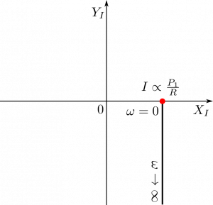
This is a response to a question whether Nyquist plot position for IMPS reveals cathodic/anodic currents.
In Intensity Modulated Photocurrent Spectroscopy (IMPS), intensity modulated light $P(t)$ stimulates photocurrent $I(t)$ in an illuminated sample. Both the light modulation and the photocurrent are periodic functions of time.
X-Y Nyquist plots (Argand diagrams)
A Nyquist plot shows periodic signal components in X-Y plane, where $X$ is “In-phase” component and $Y$ is “Quadrature” component.
A mathematical form of $X$ and $Y$ depends on the choice of a mathematical representation of the stimulus.
If the stimulus has the form
$$
P = P_0+P_1\cos(\omega t)
$$
$X$ would be
$$
X = \frac{2}{T}{\int_0}^{T} \cos(\omega t) I(t) \mbox{d}t
$$
and $Y$ would be
$$
Y = \frac{2}{T} \int_0^{T} \sin(\omega t) I(t) \mbox{d}t,
$$
where $T$ is the period $T= \frac{2\pi}{\omega} $, and $\omega$ is the signal angular frequency.
On the other hand if the stimulus has the form
$$
P = P_0+P_1\sin(\omega t)
$$
$X$ would be
$$
X = \frac{2}{T} \int_0^{T} \sin(\omega t) I(t) \mbox{d}t
$$
and $Y$ would be
$$
Y = -\frac{2}{T} \int_0^{T}\cos(\omega t) I(t) \mbox{d}t.
$$
General stimulus
In general, a stimulus of the form
$$
P = P_0 + P_1 \cos(\omega t + \phi)
$$
is accompanied with the following definitions of the In-phase and Quadrature
$$
X = \frac{2}{T} \int_0^T \cos(\omega t + \phi)I(t)\mbox{d}t
$$
and
$$
Y = \frac{2}{T} \int_0^T \sin(\omega t + \phi)I(t)\mbox{d}t.
$$
It is a general formulation because it contains both forms of the stimulus mentioned above. The first one is recovered by setting $\phi=0$, and the second with $\phi =- \frac{\pi}{2}$.
Our IMPS/IMVS instrument uses the $P(t) =P_0 - P_1\cos(\omega t)$ or $\phi=\pi$ stimulus to avoid rapid changes in light intensity at the start of a measurement when $t=0$ and for $P_0 = P_1$.
Photocurrent sign convention
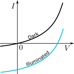
In the I-V characteristics of a Si photodiode the photocurrent has negative sign i.e., the stronger the illumination the more negative current is generated by the photodiode at a given bias voltage $V$. In short, the derivative of current $I$ with respect of light intensity $P$ is negative, $\frac{dI}{dP} < 0$.
The blue line is a result of a static i.e., $\omega = 0$ stimulus.
For the time modulated illumination at frequencies much smaller than any characteristic frequency of the photodiode
one will get the following response:
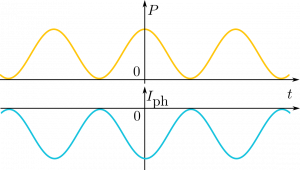
where $I_{ph}$ is the negative photocurrent. One can see it is phase-shifted with respect to the stimulus by $\pi$.
Thus, $X$ is negative and $Y = 0$. The larger the amplitude of modulation $P_1$ the more negative $X$.
Nyquist plot for Si photodiode at $\omega = 0$
A Nyquist plot of the photocurrent for $\omega = 0$ and for three light modulation amplitudes is shown below:
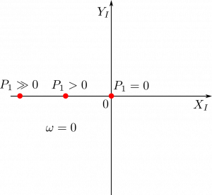
The $_I$ subscript of the $X$ and $Y$ components in axis description indicates that they correspond to electric current.
IMVS (Intensity Modulated Photovoltage Spectroscopy) does also use Nyquist plots but the “In-phase” and “Quadrature” components have the subscript $_V$.
Nyquist plot for serial RC
Case 1: $\frac{dI}{dP} < 0$
A photodiode has $dI/dP < 0$ up to its saturation, where $\frac{dI}{dP}= 0$. Let us assume incorrectly(!) that its equivalent circuit consist of just a resistance $R$ and a capacitance $C$ connected in series.
The characteristic time scale $\tau$ will be set by the $\tau = RC$ product. So will the characteristic angular frequency $\omega = \frac{1}{\tau}$.
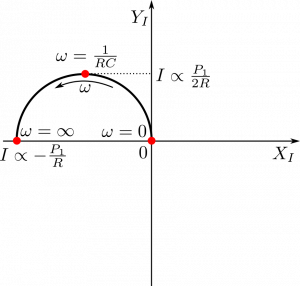
The plot above is only for positive frequencies $\omega$. Negative frequencies would provide a bottom half of the circle.
Case 2: $\frac{dI}{dp}>0$
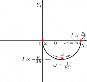
Notice, it does not matter whether the photocurrents are cathodic or anodic. What matters is the sign of the derivative $\frac{dI}{dP}$.
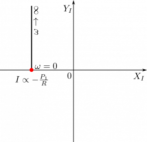
Nyquist plot for parallel RC
Case 1: $\frac{dI}{dP} < 0$
Case 2: $\frac{dI}{dP} > 0$
